 1、 Scope
This test standard serves to determine the scratch resistance of painted and unpainted plastic inte-rior components. A scratch test (crosscut test) is performed on the surface of the component to thisend.
2、 Designation
Scratch resistance acc. to PV 3952
3、Definition
The scratch resistance of plastics is defined as the resistance offered by the material to a mechani-cal stress, e.g. scratching motion of a sharp edge or rounded object.
4、Requirements
Requirements and deviations from the test procedure according to the technical supply specifica-tion and/or release.
5 Test
Principle
5.1
A machine-guided scratching gouge scratches a grid with a spacingof approx.2 mm onto apainted/unpainted plastic surface. Each scratch is produced by one movement in one direction.colorimeter is then used to determine the chromatic aberration in relation to the unscratched sur.face.
5.2Test equipment and auxiliary equipment
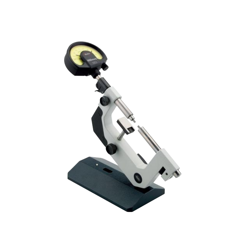
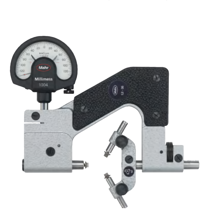
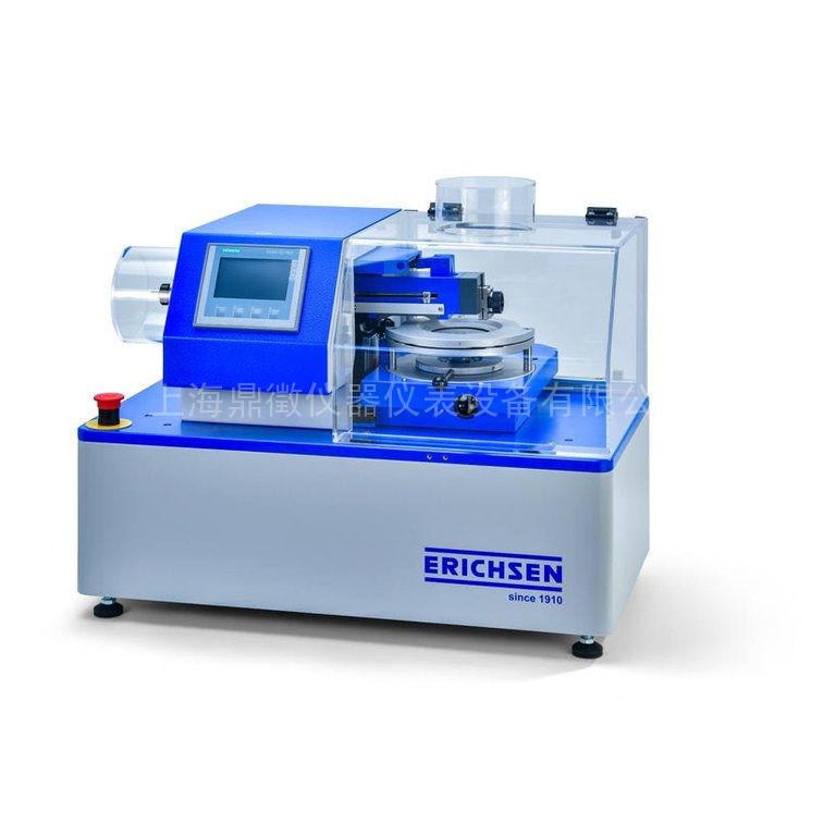
Scratching device (e.g. motor-driven crosscutting tool, from Erichsen, model 430; see Figures1 and 2)
Scratching gouge (e.g. hard metal tip ② = 1 mm; the engraving tip of the 318 hardness testingdevice from Erichsen is suitable)Colorimeter acc. to DlN 5033-4
Measurement shapes acc. to DIN 5033-7 section 3.2.1 - 45°/ 0° or section 3.2.2 - 0°/ 45°(ideal 45° circular)Other shapes are also permissible upon agreement with the test laboratories.Visual evaluation under standard light acc. to DlN 6173 Parts 1 and 2Standard light D65 (minimum requirement: quality grade 2)
5.3 Specimen
The specimens must be removed from the components under test and should be of a shape andsize that ensures plane contact with the specimen holder and the supporting table of the respectivespectrophotometer, The test surface must be plane parallel with the contact surface.
5.4 Specimen preparation
The surface of the specimens must be homogeneous and must have no foreign matter. Specimensshould only be handled with clean, grease-free hands.
5.5 Conditioning
The specimens must be conditioned for a minimum of 48 h in a standard climate according toDIN 50 014-23/50-2.
5.6 Procedure
The test is performed at (23 ± 5)°C.
A scratching tool is used to scratch a grid (crosscut grid) of at least (40 x 40) mm. See Figure 3.
Testing parameters:
Contact force:F=5 N and 10 N(for unpainted components; Fis dependent onthe position in the vehicle and the component specifications)F=10 N(for painted components)
Scratching :speedv=1,000 mm/min
Grid spacing:2 mm
Scratching gouge:Φ1 mm(e.g.engraving tip from the 318 hardness testing devicefrom Erichsen)
Calibrating the test tip with the specimenAlign the test tip flat against the test surface. The test tip must be adjusted to just before it touchesthe specimen. The test tip must not come into contact with the specimen.Notice: There must not be any additional weight on the specimen during the alignment process
For a not OK (NOK) example of the alignment process, see figure 4 For an OK example of the alignment process, see figure 5.
The N0 scale (see figure 6) is not relevant for alignment, i.e., the value on the scale difers fromNO.
Use only suitable, calibrated additional weights when setting the weight force required to carry outthe force test (e.g.,F=10 N), fiqure 7.
lf the scale setting in the X direction is not sufficient for calibration (see figure 8), additional weightsmay be required(see figure 9).
5.8Evaluation
The measured values for dL*. da*, db* and dE* of the unscratched area from the scratched areadetermined using colorimetry, are used for evaluation (measured value = mean of at least 5 indi-vidual measurements).
Measuring method acc. to DlN 5033-4
Color change acc. to DlN 6174
llluminant: D65 /10°
Measuring field diameter: ≥ 7 mm
In addition, a test of the measured values for plausibility of the optical impression must be per-formed (even when the measurements indicate an evaluation of OK).
1、 Scope
This test standard serves to determine the scratch resistance of painted and unpainted plastic inte-rior components. A scratch test (crosscut test) is performed on the surface of the component to thisend.
2、 Designation
Scratch resistance acc. to PV 3952
3、Definition
The scratch resistance of plastics is defined as the resistance offered by the material to a mechani-cal stress, e.g. scratching motion of a sharp edge or rounded object.
4、Requirements
Requirements and deviations from the test procedure according to the technical supply specifica-tion and/or release.
5 Test
Principle
5.1
A machine-guided scratching gouge scratches a grid with a spacingof approx.2 mm onto apainted/unpainted plastic surface. Each scratch is produced by one movement in one direction.colorimeter is then used to determine the chromatic aberration in relation to the unscratched sur.face.
5.2Test equipment and auxiliary equipment
Scratching device (e.g. motor-driven crosscutting tool, from Erichsen, model 430; see Figures1 and 2)
Scratching gouge (e.g. hard metal tip ② = 1 mm; the engraving tip of the 318 hardness testingdevice from Erichsen is suitable)Colorimeter acc. to DlN 5033-4
Measurement shapes acc. to DIN 5033-7 section 3.2.1 - 45°/ 0° or section 3.2.2 - 0°/ 45°(ideal 45° circular)Other shapes are also permissible upon agreement with the test laboratories.Visual evaluation under standard light acc. to DlN 6173 Parts 1 and 2Standard light D65 (minimum requirement: quality grade 2)
5.3 Specimen
The specimens must be removed from the components under test and should be of a shape andsize that ensures plane contact with the specimen holder and the supporting table of the respectivespectrophotometer, The test surface must be plane parallel with the contact surface.
5.4 Specimen preparation
The surface of the specimens must be homogeneous and must have no foreign matter. Specimensshould only be handled with clean, grease-free hands.
5.5 Conditioning
The specimens must be conditioned for a minimum of 48 h in a standard climate according toDIN 50 014-23/50-2.
5.6 Procedure
The test is performed at (23 ± 5)°C.
A scratching tool is used to scratch a grid (crosscut grid) of at least (40 x 40) mm. See Figure 3.
Testing parameters:
Contact force:F=5 N and 10 N(for unpainted components; Fis dependent onthe position in the vehicle and the component specifications)F=10 N(for painted components)
Scratching :speedv=1,000 mm/min
Grid spacing:2 mm
Scratching gouge:Φ1 mm(e.g.engraving tip from the 318 hardness testing devicefrom Erichsen)
Calibrating the test tip with the specimenAlign the test tip flat against the test surface. The test tip must be adjusted to just before it touchesthe specimen. The test tip must not come into contact with the specimen.Notice: There must not be any additional weight on the specimen during the alignment process
For a not OK (NOK) example of the alignment process, see figure 4 For an OK example of the alignment process, see figure 5.
The N0 scale (see figure 6) is not relevant for alignment, i.e., the value on the scale difers fromNO.
Use only suitable, calibrated additional weights when setting the weight force required to carry outthe force test (e.g.,F=10 N), fiqure 7.
lf the scale setting in the X direction is not sufficient for calibration (see figure 8), additional weightsmay be required(see figure 9).
5.8Evaluation
The measured values for dL*. da*, db* and dE* of the unscratched area from the scratched areadetermined using colorimetry, are used for evaluation (measured value = mean of at least 5 indi-vidual measurements).
Measuring method acc. to DlN 5033-4
Color change acc. to DlN 6174
llluminant: D65 /10°
Measuring field diameter: ≥ 7 mm
In addition, a test of the measured values for plausibility of the optical impression must be per-formed (even when the measurements indicate an evaluation of OK).
- 范围:
本测试标准适用于喷漆与非喷漆塑料内饰零部件的耐划伤系数确定。耐划伤测试(横切测试)需在零部件的表面进行。
- 指定命名
耐划伤参见PV3952
- 定义
塑料件耐划伤是指材料抵抗机械压力的性能, 如:锋利边或圆形物体的刻划动作。
- 要求
本测试程序的要求参见供货技术规范或放行要求。
- 测试
5.1 原理
在喷漆或未喷漆塑料件表面用带机械臂的圆凿划出一个大约2MM的格子。每个划痕只能朝单一方向刻画一次。然后用色度计,与未划痕表面进行色差比较。
5.2 测试设备与辅助设备
* 刻划设备(如:电动的横切工具,德国仪立信测厚仪,型号430,参见图1与图2)
* 刻划圆凿(如:硬金属尖,直径为1MM,如德国318仪立信硬度测试设备)
* 色度计参见DIN5033-4
* 测量形状参见DIN5033-7, 第3.2.1--。。。。。
若实验室许可,其它形状亦可。
*在标准光线下进行外观评估,参见DIN6173第1与2部分
*标准光线D65(*低要求:质量等级2)
5.3 样品
样品须为测试零部件的一部分,其形状与大小须满足测试要求,即:须确保样品与其固定装置平行接触,并与分光光度计的支撑桌面保持平行。测试表面必须与接触面保持平行。
5.4 样品准备
样品表面须保证同质性,不得含有任何其他物质。且须对样品进行清洁。不得使用油腻的手直接接触样品。
5.5 作用条件
样品须在标准气压下至少存放48小时,参见DIN50 014-23/50-2
5.6 程序
测试须在23+-5度条件下进行。
使用刻痕工具刻划出一个至少为40*40MM的格子。参见图3
测试参数:
*接触力: F=5牛与10牛(对为喷漆零部件,力的大小取决于其在机车中的位置与零部件要求)
*刻划速度:V=1000MM/分钟
*格子大小: 2MM
*刻划圆凿: 直径1MM(如:德国德国仪立信318硬度测试设备)
图1
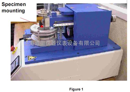
图2

5.7 评估计算
使用色度计,获取测试值:dL*, da*, db*,并用测试值进行评估(测试值=每个值5次测量后所获得的值的平均值)。
测量方法参见DIN5033-4
颜色变化参见DIN6174
照明度:D65/10度
测量区域直径:大于等于7MM
- 参考标准
DIN 50014 气候与技术应用,标准气候
DIN5033-4 比色法,光谱法
DIN5033-7 比色法,物体颜色测量条件
DIN6173-1 颜色取样,通用颜色取样条件
DIN6173-2 颜色去演,人工光照条件
DIN6174 依据CIELAB公式,进行色差确定
 扫一扫,手机浏览

 上海鼎振仪器设备有限公司