扫一扫,手机浏览
- 技术文章
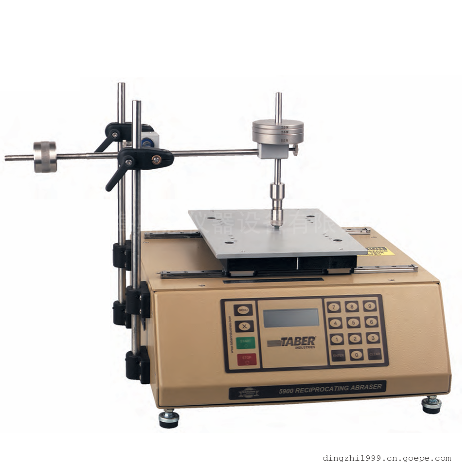
福特汽车FLTM BI107-05油漆附着力热冲击试验标准
2018-02-07 17:15:45 来源:上海鼎徵仪器仪表设备
Application
This procedure is used to determine the resistance to coating adhesion loss of coated surfaces of aluminum,plastic, steel, and other substrates when subjected to a wet blast similar to that produced by vehicle wash equipment.Apparatus and Materials Required
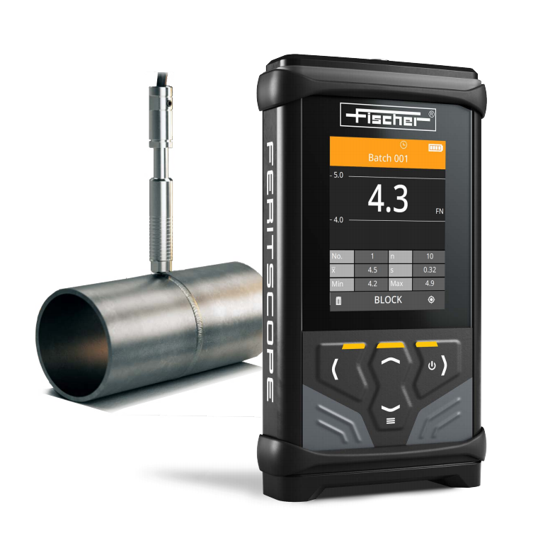
Film Thickness Gauge
per Ford Laboratory Test Method BI 117-01
Carbide Tip Scribe
CTS (General Scribe #CM 88) - or equivalent
12015 Telegraph Rd.
Detroit, Michigan U.S.A.
(313) 531-7668
Utility Knife
Stanley, Quick Point 10-300 - or equivalent
(break away tips)
Water Immersion Tank
Per Ford Laboratory Test Method BI 104-01
Note: Thermal shock testing requires:
a. 38 +/- 2 °C water temperature
b. 5 ppm maximum dissolved solids
Heater/Circulator
Fisher Scientific 13-874-70J - or equivalent
Dissolved Solids Meter
Myron L Company - or equivalent
833 East Broadway
San Gabriel, California
Freezer
Capable of minus 29 +/- 2 °C temperatureSteam Generator
a. Input flow of water to be 2.7 +/- .1 L/min (*).
b. Nozzle diameter to be 12.5 +/- .3 mm ID and at least 100 mm long.
c. Discharge dynamic head to be 37.9 +/- 1.9 kPa measured 25 mm from the nozzle using
a 4.7 mm ID tube. A substantially non-diverging discharge is required for this test (**)
(***) (see Figures 1 and 2).
Note: Electro-Magic Model 100 (and the earlier Model 60) Steam Generator available only
from:Atomic Cleaning Systems, 31651 West Eight Mile Road, Livonia, MI 48150, Phone:
(248) 615-4400, has been found to be satisfactory. The Model 100 or Model 60 are no
longermanufactured directly by Electro-Magic. However, Atomic Cleaning Systems is
capable ofmodifying new Electro-Magic models to meet the Model 100 specifications
required for this test.Milwaukee 1/2 inch globe valve No. 1151-1161, 150 SWP 300 WOg
is adequate for use in standardization of generator.
Model 100 Steam Generator
The pumping pressure is directly related to the input flow rate. The pressure needed for
therequired flow can be determined by measuring the pump pressure and discharge
flow rate withthe burner off. When the burner is turned on, the required flow rate is
obtained by readjusting to the required pump pressure.
This is done by placing the tube midstream 25 mm from the nozzle. The tube size must
not bevaried because the densities and velocities are not uniform throughout the cross
section of thedischarge stream.
Adjusting the discharge dynamic head may be required. This must be done in such a
way thatthe input flow rate as specified in Para (a) above is maintained. This is done by
adjusting the amount of heat transferred to the water. Increasing the heat will cause the
flow rate (pressure) of (a) to change. It must be readjusted. This operation will result in an
increased dynamic pressure; to decrease it, decrease the heat and then adjust the flow
(pressure).Thermometer
Capable of measuring 100 +/- 2 °C
Face Mask
Full face cover safety mask is required when performing this test.
Gloves
Gauntlet-type gloves for protection of hands are required.
Conditioning and Test Conditions
All test values indicated herein are based on material conditioned in a controlled atmosphere of 23 +/- 2 ??C and 50 +/- 5 % relative humidity for not less than 24 h prior to testing and tested under the same conditions unless otherwise specified.Procedure
1. Standardize the Model 60 or Model 100 Steam Generator.
a. Measure and maintain the input flow at 2.7 L/min. Install a 12.5 mm globe valve in the
steam line between coil weld assembly and a 5/32 inch hose nipple. With burner off,
engage pump and adjust globe valve until 2.7 L/min is obtained.
Record the tank pressure that is obtained with the 2.7 L/min flow rate. (This induced
back pressure simulates the pressure that steam exerts on the system while the burner
is on.)
b. Measure and maintain the mean dynamic head at 37.9 kPa (5.5 psi) using the fixtures as
described in Figures 1 and 2. Open globe valve and turn on the burner. Allow tank
pressure tostabilize before reading the mean dynamic head. Adjustments of the
dynamic head are to be made by changing the amount of heat transferred to the water
at the burner. (The flow rate, as specified above, must be maintained.)
c. Measure and maintain a 98 +/- 2 °C temperature of the steam blast at the test
sitedistance.2. Measure film thickness per Ford Laboratory Test Method BI 117-01 at proposed test sites
and record.
3. Immerse the parts or panels (previously prepared per Engineering Materials Specification)
in the water immersion tank for four hours at 38 +/- 2 °C. Aerate the water by placing 6.5
mm ID plastic tube at the bottom of the tank and bubble air at a rate of one bubble per
second minimum. Maintain a 5 ppm maximum dissolved solids (as NaCl) in the water.
Check and record NaCl level using a dissolved solids meter.
4. Remove the samples after four hours of water immersion and cut an "X" through the
coating into the substrate across the panel or part where feasible (see Figure 3).
a. Use a scribe to make the cut if the substrate is metal or hard, rigid plastic.
b. Use a utility knife to make the cut if substrate is an elastomeric material.
5. Place the test samples in a freezer at minus 29 +/- 2 °C for a three hour minimum freeze
cycle.
6. Within 30 seconds from freezer removal, direct the steam blast at the center of the "X" cut,
at a distance of 2 to 3 inches and 45° to the sample, in the direction shown in Figure 3.
Note: High pressure wet steam represents a potential safety hazard. Not only is it necessary|
to secure the samples properly, but full face protection and gloves are required.
7. After 30 seconds, record area (mm2) of coating removal by visually measuring with a
metric ruler (typical triangular coating removal: Area = 1/2 Base x Height). Also examine
the surface and report any blushing, whitening, or loss of gloss.
8. If a failure occurs, note number of seconds after steam black initiated that the failure
occurred.
Chemicals, materials, parts, and equipment referenced in this document must be used and handled properly.
Each party is responsible for determining proper use and handling in its facilities.
ATTACHMENT ONE
RATING SCALE FOR
THERMAL SHOCK TEST PANELS
RATING PEEL BACK
20 = No removal
19 = < 0.5 cm^2
18 = < 1.0 cm^2
17 = < 1.5 cm^2
16 = < 2.0 cm^2
15 = < 2.5 cm^2
14 = < 3.0 cm^2
13 = < 3.5 cm^2
12 = < 4.0 cm^2
11 = < 4.5 cm^2
10 = < 5.0 cm^2
9 = < 5.5 cm^2
8 = < 6.0 cm^2
7 = < 6.5 cm^2
6 = < 7.0 cm^2
5 = < 7.5 cm^2
4 = < 8.0 cm^2
3 = < 8.5 cm^2
2 = < 9.0 cm^2
1 = < 9.5 cm^2
0 = > 9.5 cm^2
SEE SPECIFICATION FOR ACCEPTANCE CRITERIA RATING
Figure 1
Figure 2
Figure 3
Figure 4
-
 上海鼎振仪器设备有限公司
咨询热线 13472521719 内容声明:谷瀑为第三方平台及互联网信息服务提供者,谷瀑(含网站、客户端等)所展示的商品/服务的标题、价格、详情等信息内容系由店铺经营者发布,其真实性、准确性和合法性均由店铺经营者负责。谷瀑提醒您购买商品/服务前注意谨慎核实,如您对商品/服务的标题、价格、详情等任何信息有任何疑问的,请在购买前通过谷瀑与店铺经营者沟通确认;谷瀑上存在海量店铺,如您发现店铺内有任何违法/侵权信息,请在谷瀑首页底栏投诉通道进行投诉。上海鼎振仪器设备有限公司 电话:021-32535039 手机:13472521719 地址: 上海市嘉定区德富路1198号803室太湖世家国际大厦